In The Circuit Diagram Shown Ammeter A1 Reads 10 Amperes Sol
In the circuit shown in figure, ammeter a1 measures 10a and a2 , 4a 39. consider the following electrical circuit diagram in which nine Solved consider the circuit diagram shown below, the
In the circuit shown below, the reading if the ammeter (A) is (assuming
What is an ammeter? symbol, circuit diagram, types and applications 3. in the circuit shown, the ammeter reading will indicate Solved: 'consider the following circuit a) what would be the readings
In the circuit shown below, the reading if the ammeter (a) is (assuming
Solved 4. for the circuit shown below the ammeter reads aSolved consider the circuit shown below. the ammeter reads In the circuit shown, the reading of ammeter is 5 a and that of voltmeter..13+ ammeter connection diagram.
Solved the figure below shows a circuit diagram. the ammeterA part of a circuit is shown in figure. here reading of ammeter is 5 a an.. Ammeter in a circuit diagramSolved the ammeter (a) in the circuit shown in the figure.

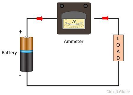
Parallel circuit with ammeter
The readings of the ammeters a1 , a2 and a3 , in the circuit shown here,..Solved 20) in the circuit diagram shown below, ammeter a1 Solved v part a in the circuit shown in the figure (figureSolved 5. what will the dc ammeter, a1, read in the.
Ammeter symbol[solved]: in the circuit shown in the diagram, the ammeter Solved in the circuit shown in the diagram, the ammeter2 in the circuit shown below, the ammeter reads 4 a and the voltmeter rea...

Solved in the circuit shown in the diagram, the ammeter
Solved 20. consider the circuit shown in the diagram. 1)Schematic diagram of ammeter 47. what will be the reading of ammeter a in given circuit as shown inDigital dc ammeter circuit diagram.
In the circuit shown below, the ratio of reading of ammeter a1, a2 andA part of circuit is shown in figure. all the ammeters are ideal. if Ammeter circuit diagramHow is an ammeter connected in a circuit how is a voltmeter connected.

From the circuit diagram shown find the voltmeter reading and the
In the circuit shown below, the ammeter reads 0.50 a when s, is closed .
.


Solved In the circuit shown in the diagram, the ammeter | Chegg.com

47. What will be the reading of ammeter A in given circuit as shown in

In the circuit shown below, the ratio of reading of ammeter A1, A2 and

Solved Consider the circuit shown below. The ammeter reads | Chegg.com
13+ Ammeter Connection Diagram | Robhosking Diagram

In the circuit shown below, the reading if the ammeter (A) is (assuming

A part of a circuit is shown in figure. Here reading of ammeter is 5 A an..

39. Consider the following electrical circuit diagram in which nine